CS 184: Computer Graphics and Imaging, Spring 2019
Project 2: Mesh Editor
Beverly Pan
Overview
In this project, I implemented a variety of mesh operations. I began by implementing operations on a (Bezier) curve, from which more complex surfaces/meshes can be made. I used de Casteljau's Algorithm to construct Bezier curves, then used more advanced concepts and interpolation to create Bezier patches. The next part of the project involved working with triangle meshes. I implemented some useful functions for triangle meshes using a halfedge data structure: averaging mesh normals (for smoother shading), edge flipping, and edge splitting. To sum normals across the mesh for averaging, I "traverse" the mesh using halfedge operations and compute cross products to find the normal of each triangle face. Implementing the flip and split functions require, in their implementation, many pointer reassignments and careful typo searches. After completing these two functions, I was able to implement loop subdivision, which allows me to upsample a mesh (which is almost like a 3D parallel supersampling, from project 1). Loop subdivision involves splitting every edge, then flipping newly made edges to make the result more regular.
After completing this project, I have a much better understanding of how programs that work with Bezier curves/triangle meshes process this data. I am also much better able to understand some of the functions of/vocabulary found in Autodesk Maya (and other 3D software).
Section I: Bezier Curves and Surfaces
Part 1: Bezier curves with 1D de Casteljau subdivision
De Casteljau's Algorithm is a method for evaluating Bezier curves, which are defined by two endpoints and any number of control points (although Bezier curves with fewer points are preferred, since high-degree polynomials are hard to interpolate). To perform this evaluation, de Casteljau's Algorithm first linearly interpolates between each pair of adjacent points and places a new control point on each edge. This process is repeated recursively using the newly-placed control points as the new points to interpolate between, until there is one point left. Or, we can think of this process repeating until we have n levels of points matching n number of original points.
Evaluating each step.
In this project, I implemented a function that will perform one step of the algorithm; that is, my function takes the latest calculated set of control points and computes the next level, retuning immediately if the Bezier curve has already been evaluated. Each time the function is called, the newly computed level of control points is stored in a vector which is added to a 2D vector, evaluatedLevels. So, I check that the Bezier curve has not been evaluated yet by checking that the size of evaluatedLevels is not equal to numControlPoints, the number of original control points. Then, I grab the latest level of control points from evaluatedLevels and calculate the position of each new position p'i using the linear interpolation (lerp) step given by de Casteljau's algorithm:
p'i = lerp(pi, pi+1, t) = (1 - t)pi + tpi+1
Part 2: Bezier surfaces with separable 1D de Casteljau subdivision
Bezier surfaces extend the basic concept of Bezier curves. A Bezier surface patch has 4x4 control points, which we can visualize as 4 Bezier curves in the u direction, and 4 "moving curves" in the v direction defined by control points on the 4 u-direction Bezier curves.
We can evaluate the patch for a surface position at parameters (u, v) using the separable 1D de Casteljau algorithm. First, we evaluate the point 'u' for on each of the 4 Bezier curves in the u direction. Next, we evaluate the point 'v' in the "moving" curve. The evaluation is done using the formula:
pn(t) = p0(1-t)3 + p13t(1-t)2 + p23t2(1-t) + p3t3
where p0, p1, p2, and p3 are the control points and pn(t) is the point we want (and is evaluated at parameter t).
Section II: Sampling
Part 3: Average normals for half-edge meshes
In this section, I implemented a function computes a vertex's weighted average unit normal by taking the area-weighted average of the normals of neighboring triangles. Since we are now using a half-edge data structure (as opposed to earlier parts, which used a sets of adjacent control points), we can use a halfedge's next(), twin(), and vertex() functions to retrieve each neighboring vertex. Mathematically, the normal vector to a triangle can be computed by taking the cross product of two edges of the triangle.
To implement this function, I create a Vector3D n that will store the aggregated normals of all the triangles surrounding the current vertex. Next, I traverse the vertex's neighboring points and add each cross product of two neighboring vertices (i.e. each neighboring triangle's normal). Finally, I return n's unit vector (using a built-in unit() function).
We can see that taking the averaged normals creates a much smoother-looking surface.
One bug I came across was normals that faced the incorrect direction (pictured below). This happened because the order of vertices used when taking the cross product changes the direction of the resulting normal. To fix the issue, I simply fixed the order of vertices in the cross product.
Part 4: Half-edge flip
In this section, I implemented a method that flips an edge. In the halfedge data structure, performing this operation requires reassigning halfedge, edge, face, and vertex pointers to the correct halfedges/edges/faces/vertices.
To implement this method, I first gathered all the relevant pointers to the edge's haledges, faces, and faces' edges, vertices, and their corresponding halfedges. I made sure to check whether the edge or its two adjacent faces are a boundary, returning immediately if they are. Next, I drew a diagram of what all these pointers should look like after the flip (pictured below). Next, I reassigned everything according to diagram I drew, making sure to not miss any typos. Luckily, I managed to type most of the code correctly the first time through - I only had to fix some minor typos on some vertex and edge pointers. Finally, I deleted some extra reassignments in which nothing changed, for code cleanliness.
Part 5: Half-edge split
Another operation that can be performed on a triangular mesh is an edge split. This operation creates one new vertex at the midpoint of the edge, as well as 3 or 4 new edges (depending on whether the original edge is deleted or reassigned).
I implemented this method in the same way as the edge flip, gathering all the relevant pointers (only this time I created a new vertex and three new edges), and then reassigning them. I ran into surprisingly few debugging issues (no typos). While a boundary edge can be split (not flipped), I did not implement this feature.
Part 6: Loop subdivision for mesh upsampling
Loop subdivision for our triangle meshes consists of splitting our current edges and flipping those that touch both an old and new edge for a more regular-looking mesh. The result of this subdivision is a smoother, rounder-looking mesh with much higher 'resolution' than the coarse base mesh.
(1 - n*u) * (original position) + (u) * (sum of neighboring vertex positions)
where n is the vertex degree and u is 3/16 if n=3, or 3/(8n) otherwise. The position of the new vertex created when splitting an edge AB is:
(3/8)*(A + B) + (1/8)*(C + D)
where C and D are the vertices across the triangle to the edge AB. While iterating through the mesh's vertices and edges to compute these new positions, I also take the opportunity to mark the vertices/edges as not new, so later flips will work properly. Next is the splitting step, where I iterate through the mesh's original edges (all edges that exist pre-split) and split them, setting the newly created vertex as new. Here, I set each newly created mesh's new position field to the current edge's new position. I also set some of the newly created edges (from splitEdge) to new, and some to not new, if they match the old edge pre-split (I do this using the halfedge structure to pick the edges I want).
Next, I flip edges if they connect and old and new vertex. This step "regularizes" the mesh triangles. Finally, I iterate through all the vertices again to set their current position to the position stored in their new position field.
As mentioned before, this loop subdivision smooths/rounds out the shape of the object. It is apparent in the dae/cube.dae file - upsampling just once considerably decreases the volume encompassed by the mesh. After upsampling the cube.dae file some more times, the final shape taken is a bit lumpy and asymmetrical. The asymmetry comes from the fact that the original cube mesh has only one edge splitting each cube face in an asymmetrical manner. To fix this, I preprocessed the mesh by splitting all edges along the cube's flat faces. Now when I upsample, the result is much more symmetrical and cube-like:
Section III: Mesh Competition
Part 7: Design your own mesh!
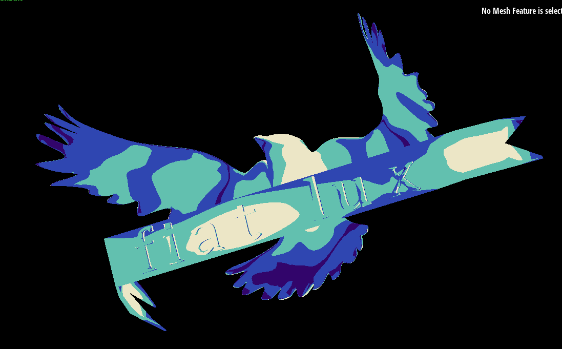
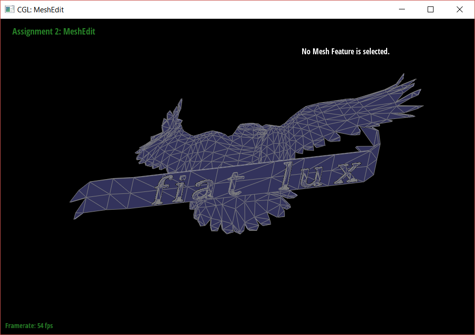
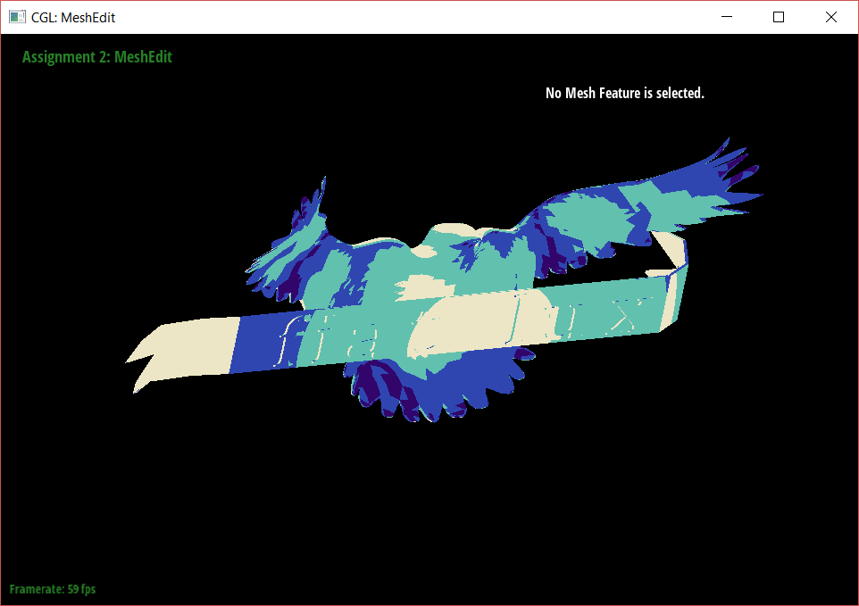
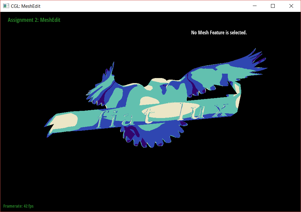
I created this model of a falcon and "Fiat Lux" banner in Maya, using 3D modeling techniques I learned in Berkeley's animation classes. Exporting the mesh from Maya as a .dae file was very bothersome - the mesh needed to be triangulated, centered, pivots centered, oriented to face up in the z direction (rather than the y), and then scaled down to a tiny size. Even after all these steps, the mesh appears darker in the MeshEdit viewport, as if its normals are flipped (which they seem to be). However, the shaders I applied seem to work just fine despite the inverted mesh.
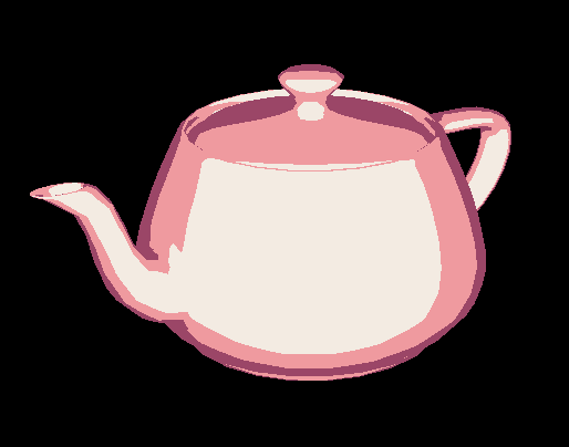
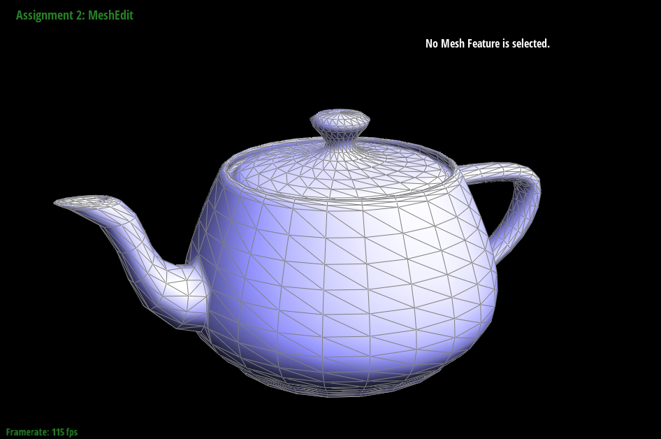
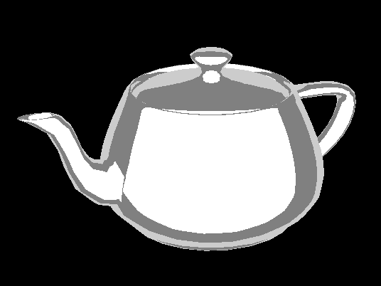
To make the cel shaded look, I modified the frag file in the shaders folder in our project. By emulating some code already written in the file, I was able to make a shader that applies any flat color to any parts of the mesh whose diffuse value is between any specified range. I experimented with this effect using the teapot.dae file before applying it to my bird model.


