CS 184: Computer Graphics and Imaging, Spring 2019
Project 4: Cloth Simulator
Beverly Pan
Overview
In this project, I implemented a cloth simulater using a mass and spring system. I first built the cloth by adding masses to a point_masses vector, then adding springs of different types to a springs vector. These springs included structural, shearing, and bending constraints. Next, I implemented the actual simulation. At each point mass, I accumulated all the external forces (mostly just gravity) and all the spring correction forces. Then, I computed the mass' new positions using Verlet integration, updating positions as long as the point mass is not pinned. Finally, I implemented a feature to the cloth sim that constrains the deformations of the cloth, ensuring that each point does not move too much. To do this, I check each pair of point masses and update positions so that the distance between each pair is at most 10% greater than the rest_length. Once my simulation was created, I added some ability to collide with other objects, namely a sphere, a plane, and the cloth itself. Sphere and plane collisions were both very similar: if the cloth is inside the sphere or has crossed the plane in the last time step, then I should "bump" the cloth back to the outside of the sphere/other side of the plane. However, cloth self-collision was much more complex; to implement this, I first had to implement spatial hashing to quickly access each point mass. Once my hash map is built, I check each point mass against the others in its hash bucket and make sure that each pair is 2 * thickness apart.
Finally, in the last part of this project, I implemented a set of shaders using glsl. I implemented diffuse shading, Blinn-Phong shading, texture mapping, bump and displacement mapping, and mirror shading.
After this project, I am much better able to understand how to translate physics to code. I also feel much more comfortable with glsl, which I had been trying, but unable, to understand while I was working in Maya.
Part I: Masses and Springs
In this part, I built the cloth by adding point masses to a point_mass vector and adding different types of springs to a springs vector.
To add to the 1D point_mass vector, I added masses in row-major order. I added num_width_points x num_height_points total masses, over width x height lengths, calculating each (x,y) index by: (width * i / (num_width_points - 1)), (height * j / num_height_points - 1) where i and j are my for loop indices. I account for a horizontally vs. vertically oriented cloth by varying my point mass positions over either the xz plane (horizontal orientation, y-coordinate in the Vector3D is 1.0) or the xy plane (vertical orientation, z-coordinate is a small random offset between -0.001 and 0.001). Next, I check whether each mass is pinned or not. Since there is a vector pinned that contains only the (x,y) indices of pinned point masses, I simply iterate through those indices and set the point mass's pinned value at each of these indices to true.
After creating all my point masses, I added the three different kinds of springs to the springs vector. I do this by iterating through my point masses, and adding constraints from it to the points around it, following the rules of each constraint (structural, shearing, or bending).
Part II: Simulation via Numerical Integration
In this part, I implemented a basic cloth simulation that responds both to external forces (like gravity) and spring correction forces (based off the springs I created in part 1).
I began by calculating the external forces, using F = ma. Since these forces apply to all point masses, I simply add the external forces to each point mass's forces. Next, I calculate the spring correction forces, computing them using Hooke's law. If a spring type is not enabled, I do not accumulate its force; if it is, I add the force to the point mass on one end of the spring and an opposite force to the point mass on the other end of the spring.
Next, I updated the positions of the point masses. To do so, we need to integrate velocity and acceleration - however, we can use Verlet integration to easily find the position updates. In addition to Verlet integration, I added some damping to the simulation to account for loss of energy by adding a (1-d) term, where d is a (very small) damping value.
Finally, I added an interesting constraint feature to the simulation. I check that each point mass's position has not changed too much/become too far away from its adjacent point mass, using a maximum distance between point masses to be (1.1 * rest_length). If the distance is too far, I change the mass's positions to be my max distance apart, multiplying by a unit vector of (point mass a - point mass b) the right direction. If one of the point masses is pinned, I apply the entire correction to the unpinned point mass; if both masses are pinned, I apply half of the correction to both masses.
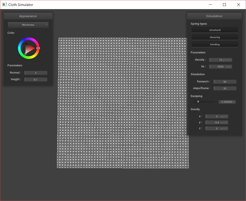
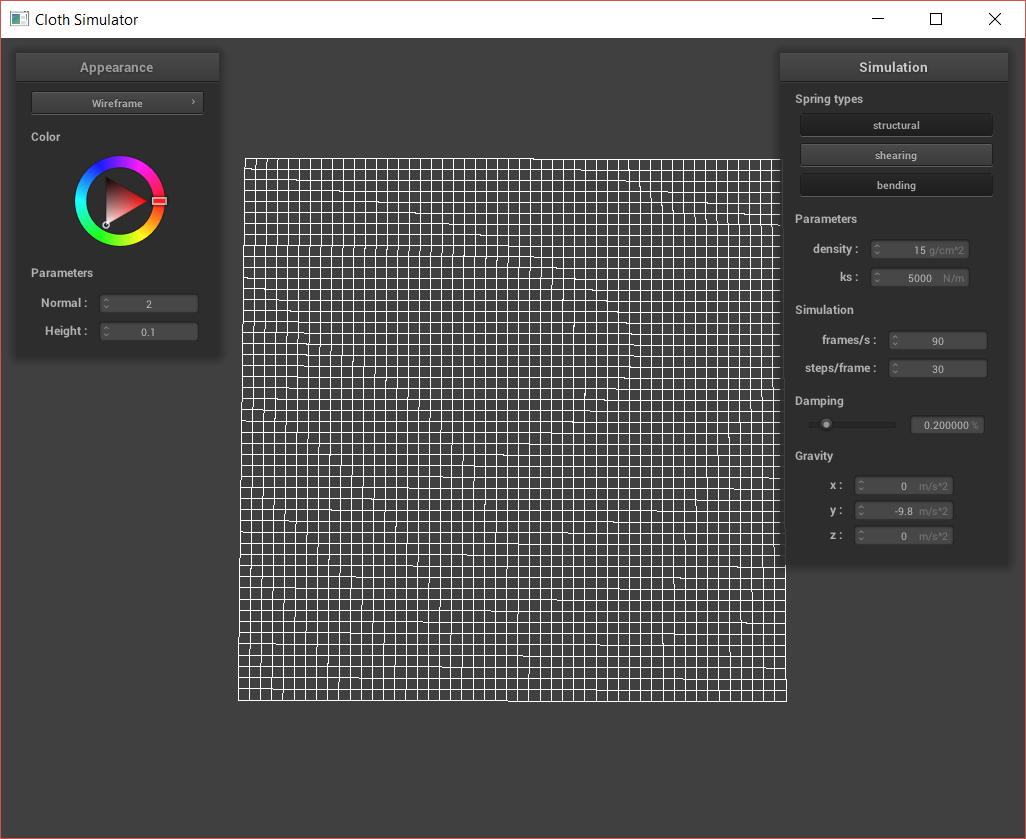
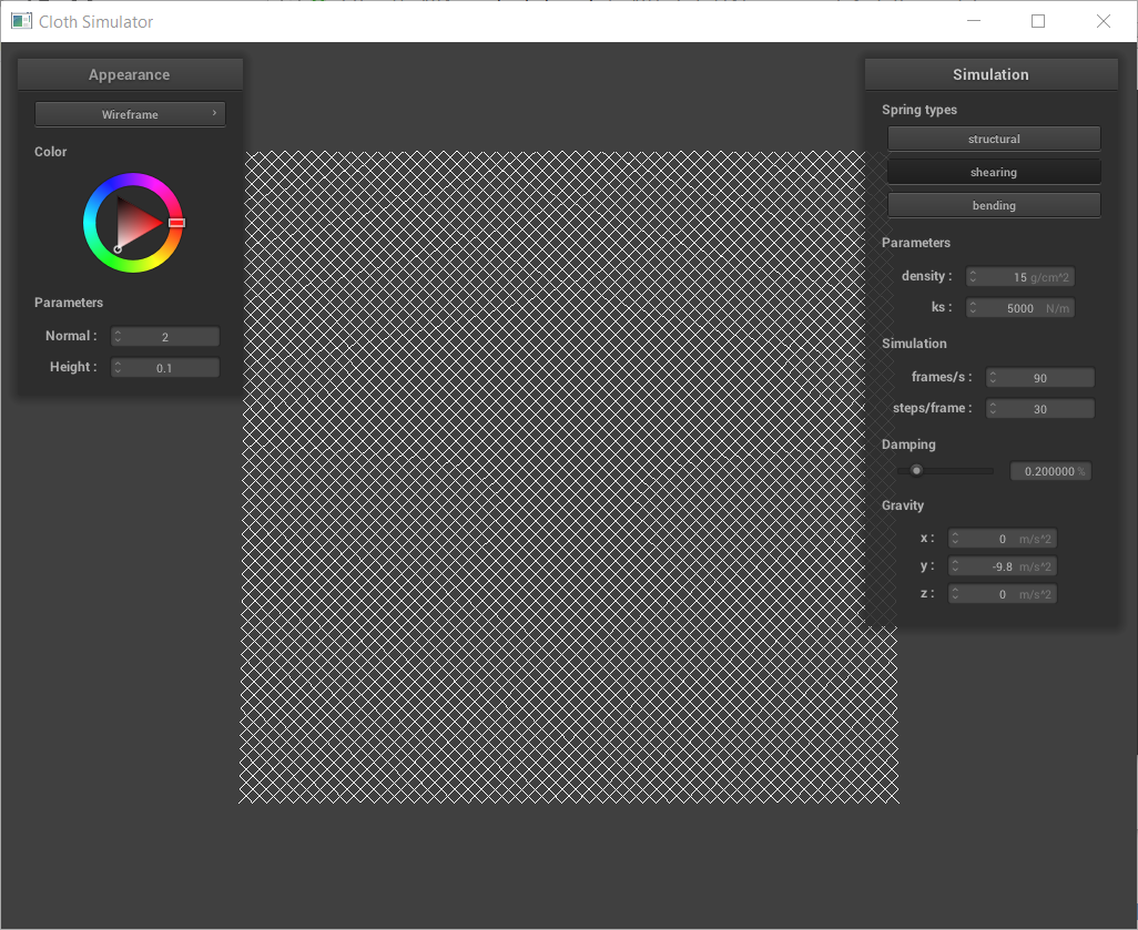
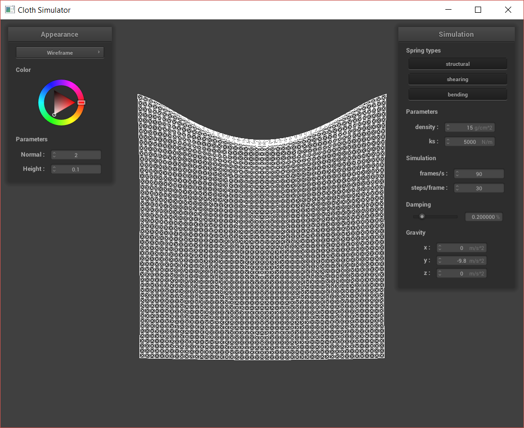
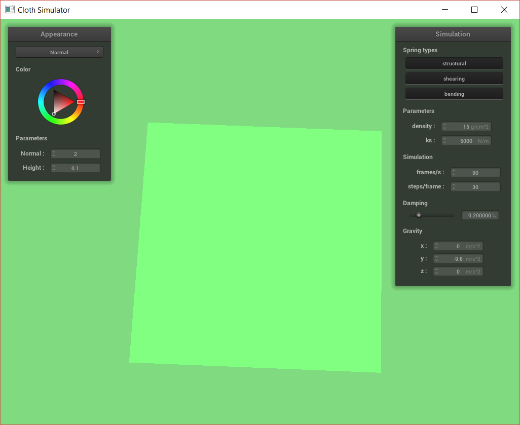
Cloth sim, default params.
After completing the basic simulation, I can play around with testing different values for ks (spring constant), density, and damping.
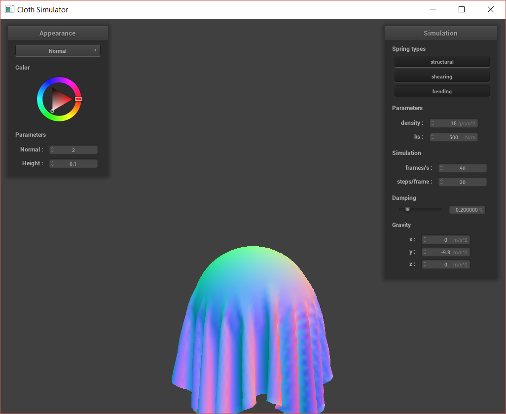
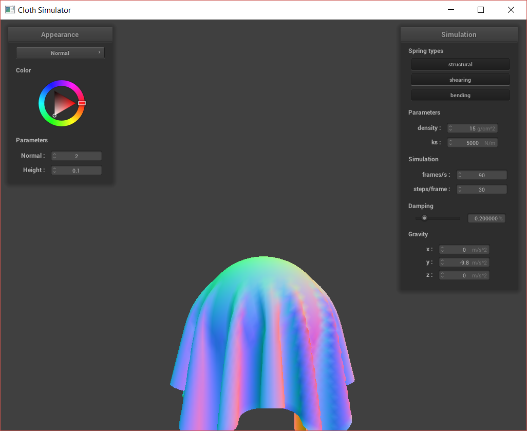
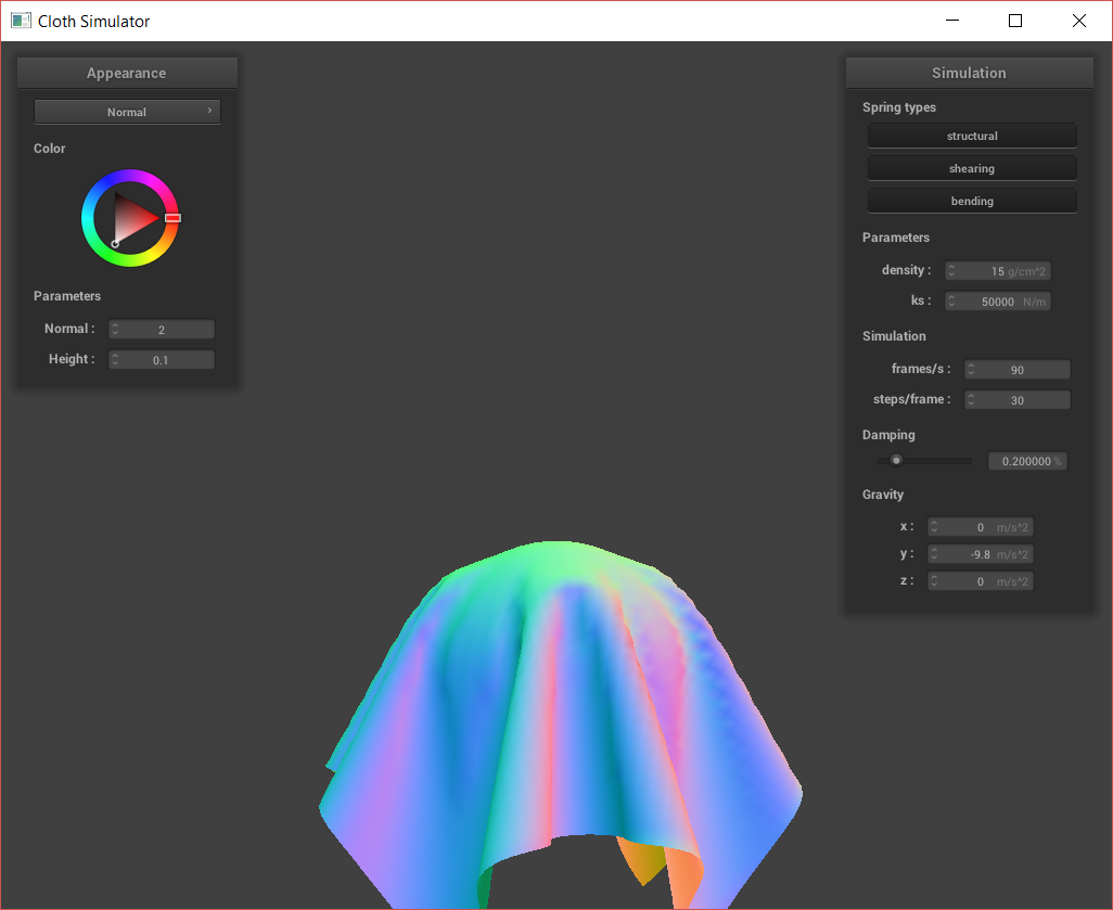
The ks value, spring constant, refers to how stiff/stretchy the spring is. A small spring constant refers to a very springy spring; when I adjusted my ks to be 50, the cloth acted very flexible and had many smaller wrinkles. It also bounced a bit harder at the end of the sim, as the springs stretched easily. On the other hand, when I used a high spring constant, the cloth seemed much stiffer and less bendable. Instead of ever having many small wrinkes where the cloth gathers due to the pins, there was only one large fold as if the cloth were made of something like burlap. My experiments are shown below:
Cloth sim, ks = 50.
Cloth sim, ks = 50,000.
Next, I tested different densities. When I tested density = 1, the cloth seemed very light. A higher density in the same volume means the cloth is heavier, so when I tested density = 1000, the cloth behaved much differently. The final resting state of the cloth showed a lot of downward pull in the cloth, as if the cloth were very heavy. There were many folds, compared to the very small folds that occured in density = 1.
Cloth sim, density = 1.
Cloth sim, density = 1000.
Finally, I changed the damping parameters. Damping refers to how much spring oscillations decay; so, a smaller damping value refers to less loss of energy and a higher damping value is a higher loss of energy. With the default damping parameter at 0.15, the cloth falls and swings a few times before coming to a stop. When I set the damping parameter to 0, there was no loss of energy and the cloth just bounced around wildly back and forth. On the other hand, when I set the damping parameter to 1, the cloth lost all its energy right away so the only movement it had was one downward sweep into the final resting state. One thing that I found very interesting was how slowly the cloth moved at damp = 1. With realistic parameters, the cloth is expected to accelerate down and have highest velocity at the point where the cloth is the lowest (like a pendulum), and have lowest velocity when the cloth is at its highest points. However, as shown in my recording below, when the damping parameter is 1, the cloth actually decelerates very slowly into its final position.
Cloth sim, damping = 0.
Cloth sim, damping = 1.
Below is a "fun" video of my simulation while I still had a bug. This occurred before I completed the constraint feature; I fixed this particular problem after realizing that .norm() and .normalize() are two quite different functions. Warning - jumpscare imminent.
A "fun" video of my clothsim while it still bugged out.
Part III: Handling Collisions with Other Objects
In this part, I implemented the ability for the cloth to interact with spheres and planes. Before beginning, I updated my cloth's simulation function to check for potential collisions with every object at each point mass so my changes in the sphere/plane files will run.
For spheres, I want to make sure that none of the cloth's point masses are inside the sphere. So, if a point mass is inside the sphere, I want to push it outside of the sphere. First, I check if the point mass is inside the sphere by checking the distance the point mass is away from the center. If the distance is smaller than the sphere's radius, I know that it is inside the sphere so I continue updating its position. Next, I find the point on the sphere's surface on the ray originating at the sphere's center, in the direction of point. This was simply found using (radius * dir + origin), where dir is a vector I made of the direction from the sphere center and the point mass's position, and radius and origin refer to the sphere's radius and center. Next, I added a correction vector the point mass so that it will reach this point. Finally, I update the point mass's position to be its last position + my correction. I scaled my correction by a term that accounts for friction, (1 - friction) before updating the position.
For plane intersections, we use a slightly different metric to figure out whether the point mass has intersected or not. In this case, we know that the mass has had an intersection with the plane if it has crossed over the plane within the last step. So, if pm.last_position is on a different side of the plane than pm.position, we know that we need to apply a correction to pm's position so that it is bumped back over to the right side of the plane. If this check (which is easily found by checking whether the dot products of the plane's normal and the vector between pm.position/pm.last_position and a point on the plane is negative) is true, we then find the point where the point mass should intersect the plane. This is simply the projection of the point mass over the plane. Next, I compute a correction vector that I can add to the point mass's position to bump it to a valid location, (i.e. on the other side of the plane). Here, I also use a small offset for the point mass to reach a point slightly above the plane.
Cloth-plane interaction, default params.
Below is a recording of a buggy interaction with the sphere. I fixed this by making sure I normalized only the vectors that needed to be normalized.
Cloth goes bye-bye
Part IV: Handling Self-Collisions
In this part, I implemented the ability for the cloth to collide with itself.
In order to speed up the process of finding testing for a self-intersection, I implemented a hash map that places masses into buckets based of the masses' positions. I first wrote a function to find the key a point mass should be added to, using (x*prime) + (y * pow(prime, 2)) + (z * pow(prime,3)) where prime is a prime number chosen at random (I used 3) and x, y, and z are the truncated coordinates from the point mass's position, scaled to the closest 3D box. Next, I add point masses to my hash map using this function. Then, I implemented the self_collide function that looks for any collisions against a given point mass. To implement this, I first created a pairwise_accum vector that will accumulate the adjustments (correction vectors) to the given point mass based. Making sure to not check the point mass against itself, I check whether the point mass is 2 * thickness distance away from the candidate point mass. If so, I compute a correction vector to push the current point so that it will be at least 2 * thickness distance away from the candidate. I accumulate this correction into my pairwise_accum. If I have accumulated at least one of these points, then I average the pairwise_accum vector - dividing each component by the number of candidate points. I also divide the pairwise_accum components by the simulation_steps variable, to help scale the position correction and improve the accuracy of this self-collision check. Finally, I updated my cloth's simulate method to check for self-collisions, similarly to how I updated it earlier to check for object collisions.
Self-collision, default params.
Below, I varied the Ks values of the cloth. As before, the lower Ks values show a springier cloth material. We can see this in how the cloth folds over itself many times at k = 2500, and bounces a lot before reaching its rest position. In fact, this cloth bounces so much that it actually unfolds most of itself by the rest position. On the other hand, when I set k = 7500, the cloth is stiffer and does not bounce as much. It lands in its rest position much sooner, and does not unfold itself.
Ks = 2500
Ks = 7500
I also adjusted the density values. When the density is low, the cloth looks almost papery, and folds over itself in large, curvy bends. When the density is high, the cloth acts more like silk, folding over itself in many small folds.
Density = 1
Density = 30
Part V: Shaders
In this section, I implemented shaders using GLSL. Shaders are useful because they run computations in parallel on the GPU as other computations (such as raytracing) occur in the CPU. They take in an input, including things like texture files or color parameters, and output a single 4D vector that carries information about vertex, such as the color or displacement at the location specified. In OpenGL, there are vertex shaders and fragment shaders. Vertex shaders apply transformations to the vertices, such as displacement. On the other hand, fragment shaders find the attributes on fragments, which are created after rasterization.
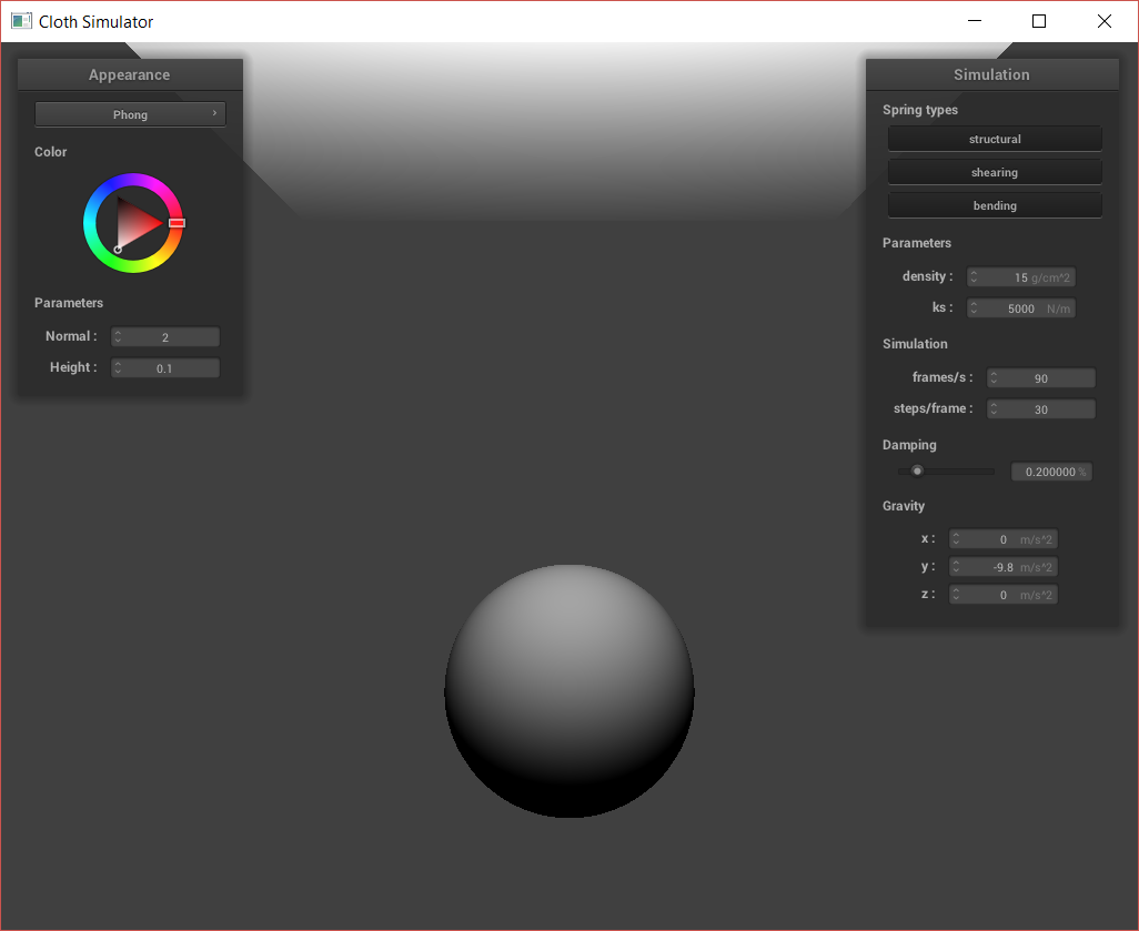
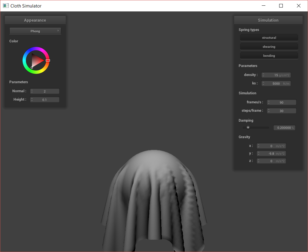
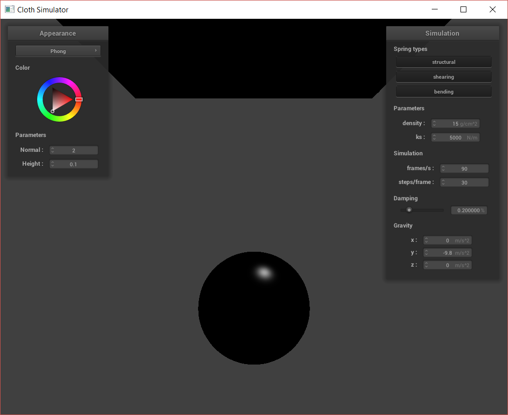
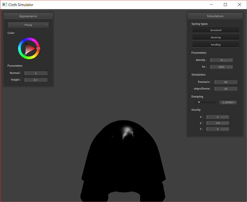
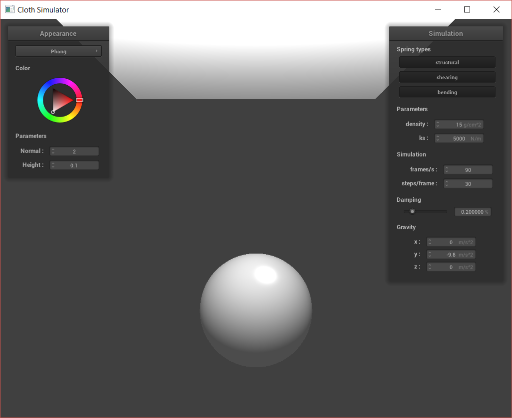
I first implemented a diffuse shader. I use this diffuse shader's calculations as part of the Blinn-Phong shader in the next part, so images are below.
In the Blinn-Phong shading model, we can account for some ambient lighting, diffuse lighting, and specular highlights. Each of these components is represented by its own term in the shading/lighting calculation.
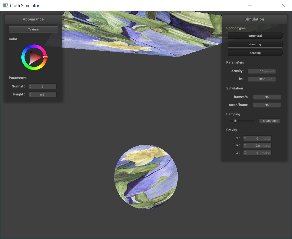
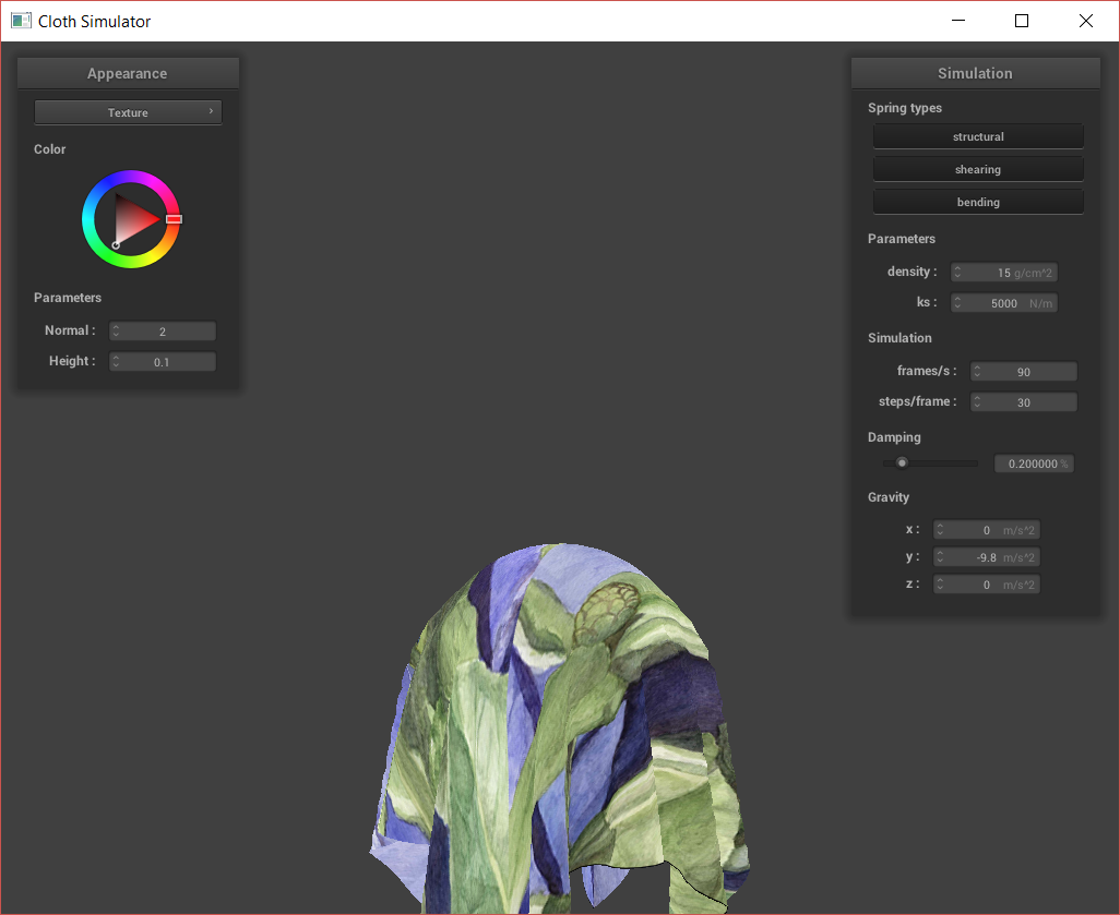
Next, I implemented texture mapping. I did this by sampling from the texture using GLSL’s texture() function.
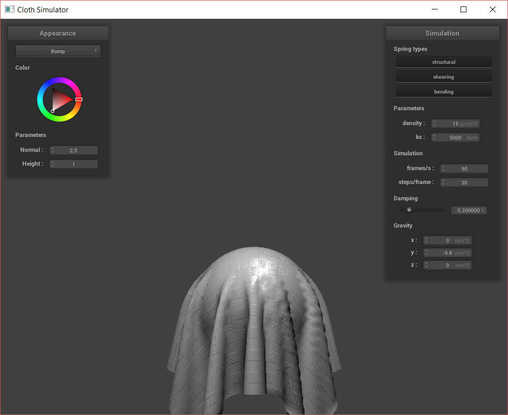
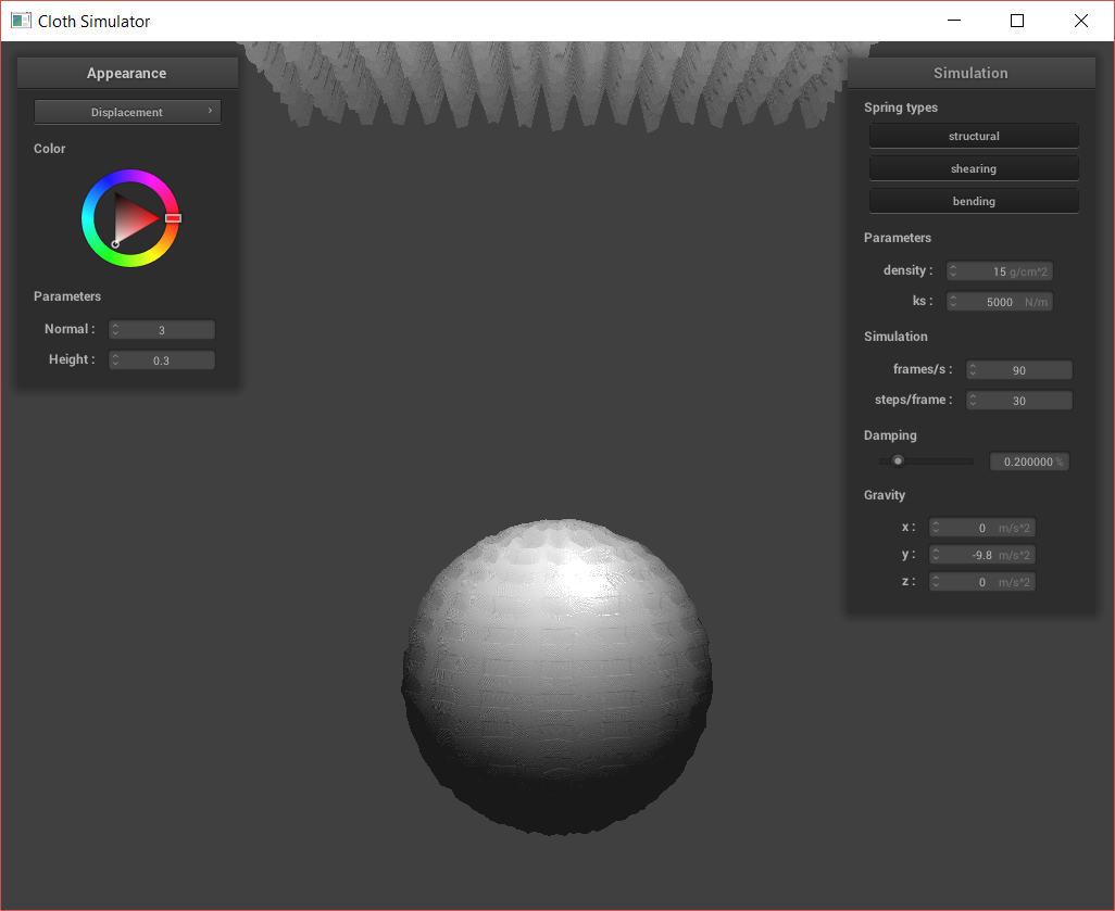
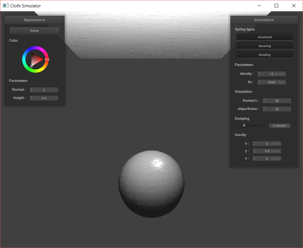
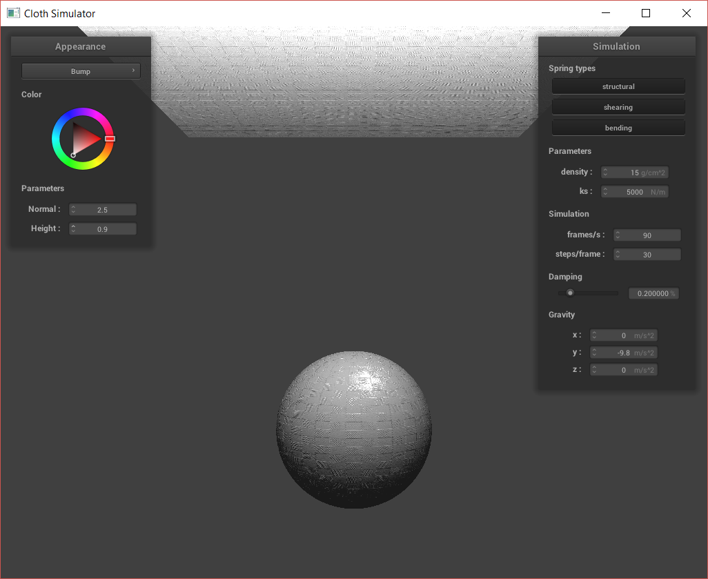
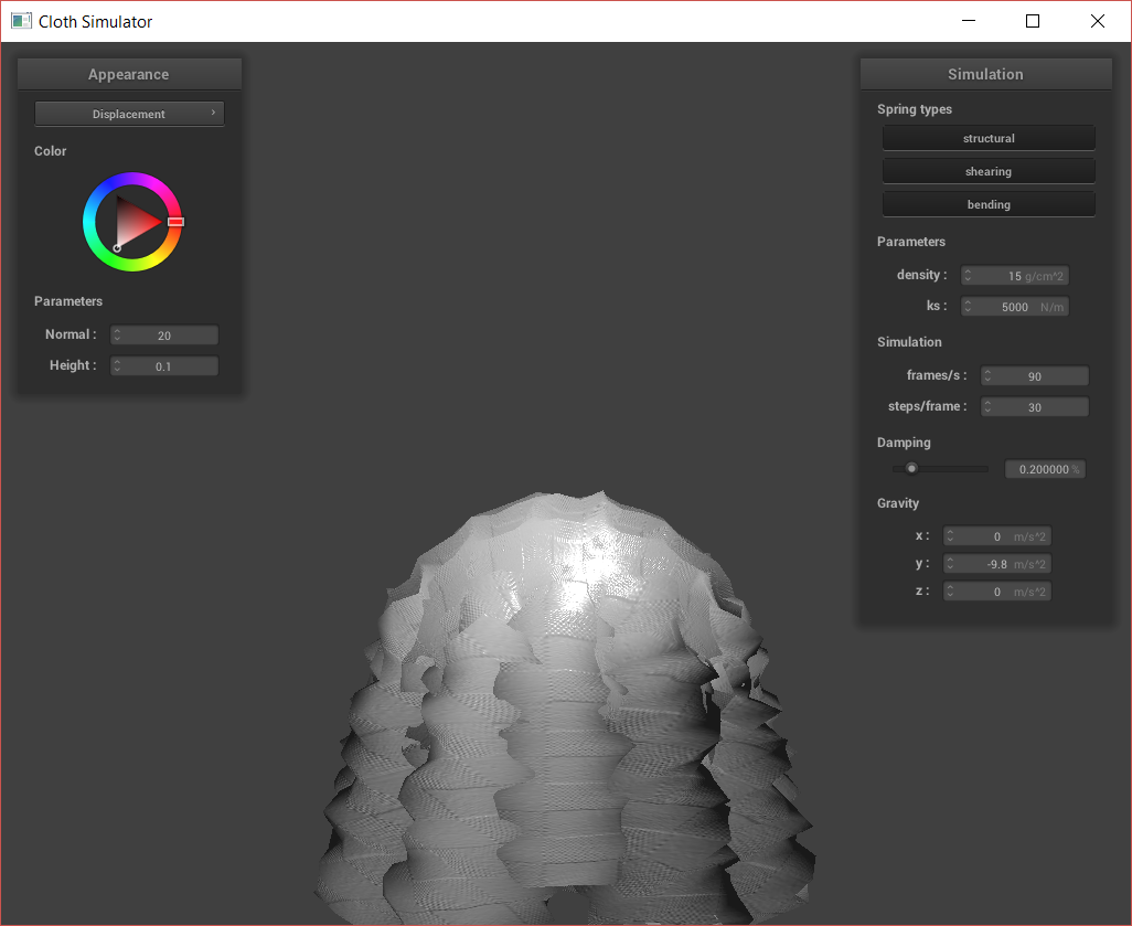
Next, I created bump and displacement maps. For bump maps, I modify the fragment shader to shade the surface using surface normals as specified by the bump map texture. However, for the displacement map, I also modify the vertex shader on top of the fragment shader. This is because I use the vertex shader to displace the actual vertex, changing the silhouette of the shapes.
Above, we can see that the bump map does not affect the silhouette of the sphere or cloth. However, the displacement causes the actual vertices of the sphere and cloth to be moved. We can also look at how the bump vs. displacement acts at different resolutions:
In the above images, the normal was held constant at 20 while the height was as high as possible for me to actually run the software. We can see that at the low coarseness, there is basically no difference between the bump and the displacement; with how difficult it was to run the displacement, we might as well use just the bump. At high coarseness, the normal map is clearly more accurate to what we might want in application. The displaced vertices are also correctly placed, with sharper edges where there exist sharper edges. However, it was even more difficult getting the displacement to show up without the program freezing, as the displacement actually changes vertex positions and is prone to funky outputs.
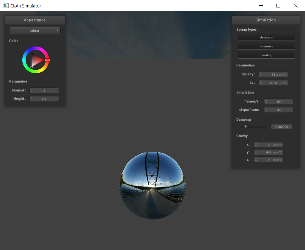
Finally, I created a mirror shader that samples an incoming radiance, using an environment map. To implement this, I simply reflect the eye vector over the normal at the surface, to get the incoming direction.

