
CS 184: Computer Graphics and Imaging, Spring 2019
Project 3-2 PathTracer
Beverly Pan


Overview
In this project, I added new features to a basic physically-based renderer, created in the first half of this project. In the first two tasks, I implemented some different materials: mirror (perfect specular reflection), glass (using refraction), and metals (using the Microfacet model). Next, I implemented environment lighting, which gives radiance from all directions in a sphere. The sphere is mapped with a texture map that defines the intensity of light from each direction. Environment lighting produces incredibly beautiful renders that show objects with what seem to be a lot of lighting detail - without the cost of using many lights. Finally, I implemented depth of field, which uses a thin lens camera model (as opposed to a pinhole model, which keeps all objects in the scene in focus).
From this project, I have learned a variety of different concepts about materials and lights. Being able to use the Microfacet model to create different kinds of conductors, using real materials' refractive indices at different wavelengths, was incredibly enlightening. Also, I enjoyed the chance to implement environment lighting because it reminds me of another (animation) project I am working on in CNM 190. In this project, our team needed a matte painting that wraps around a giant setting, so our matte painter uses Photoshop to paint it in 3D so we can map the image onto a sphere in compositing. I wonder if we could use the matte as a texture for an environment light as well.
Part 1: Mirror and Glass Materials
In this part, I implemented mirror and glass materials. To do this, I first implemented a reflect function that takes in a vector and returns its reflection about its normal. Since BSDF calculations occur in the object coordinate space, the normal vector is simply (0, 0, 1). For my mirror surface, I use this reflect function to find my output vector, and return this vector divided by the (absolute value of) the cosine of this vector with the normal.
To implement the glass material, I also needed a refraction function. Using Snell's Law, I created a refract function that takes an input vector and assigns the pointer to an output vector to the resulting refraction. The function itself returns a boolean value to determine whether or not refraction actually happens. Refraction does not occur when:
1 - η2(1 - cos2θ) < 0
which indicates that there is total internal reflection. I calculate η myself, using the (given) ior value, based on whether the input vector is "entering" or "exiting" the surface.
Next, I implemented the glass BSDF's sample_f function. If there is a valid refraction, or total internal refraction does not occur, I calculate Schlick's approximation to determine the ratio of reflection energy to refraction energy. (Otherwise, I simply return the reflectance divided by the cosine factor). I use my calculated Schlick's approximation, R, in a coin flip probability to determine whether to reflect or refract.


At max ray depth, m, equals 0 and 1, we get some pretty uninteresting images. At m = 0, we only see objects directly emitting light towards the camera. At m = 1, we add objects directly illuminated by the light, which does not include our spheres (so they remain black).


When m = 2, we can see the mirror. However, the glass appears dark since we still need another bounce for the light going through the material. At m = 3, we can see this is the case and the glass ball shows up. However, the mirror still shows the glass's reflection as dark.


At m = 4, the mirror shows a glassy ball. The mirror's reflection of the glass ball is one step behind what we see in the glass ball. The glass ball now refracts light onto the ground below it. At m = 5, the glass ball also refracts light on the wall next to it.

Finally, when m = 100, we see an image that is very similar to the one we already have at m = 5. This image is a bit brighter with more bleeding colors, since we are accounting for more bounces of light.
Part 2: Microfacet Material
In this part, I implemented the microfacet material model. This allows us to render a variety of metallic materials. To do so, I needed to calculate the normal distribution function (NDF) and Fresnel term (F). The NDH incorporates the material's alpha value, which detemines the material's roughness. Lower alpha values are more glossy/shiny, while higher alpha values are more rough.


In these renders, the sampling rate was fixed at 128 samples/pixel and 1 sample/light. Increasing the alpha value causes the object to appear less glossy/shiny and more rough.


In these renders, the sampling rate was fixed at 64 samples/pixel and 1 sample/light. On the left is cosine hemisphere sampling, which evenly samples over a hemisphere rays over a hemisphere. It is good for sampling diffuse BRDFs, but since the dragon is a microfacet, not diffuse, material, it produces a very noisy image. On the right is importance sampling, which prioritizes samples that have a greater impact on the image. The importance sampled render is much less noisy, with the same number of samples.

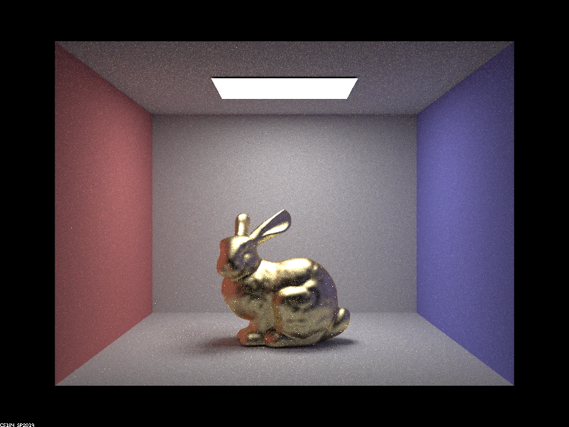
In the renders above, I changed the η and k values (alpha = 0.25) to create different bunny materials.
Part 3: Environment Light
An environment light adds light to the scene from all directions around the scene, at an "infinitely" far away distance. We can use different maps to simulate different kinds of environments for our scene. This map is what determines the incident radiance at each direction.


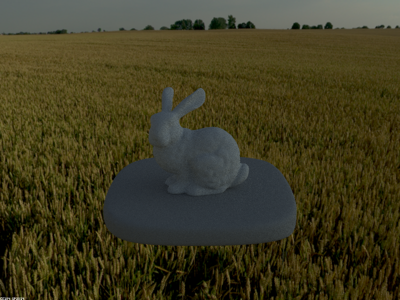


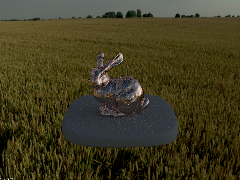
In the above renders, we can see that the importance sampled images are less noisy than the uniformly sampled images.
Part 4: Depth of Field
In this part, I implemented a thin lens for our camera.
Up until now, we have been using a pinhole camera model, which keeps everything in focus no matter how far away from the camera. This is because in a pinhole camera model, we trace a ray straight through a pinhole until it lands on some visible geometry, gather information about the radiance at that point, and display that. However, this is not very realistic to real cameras, which use lenses.
In a thin-lens camera model, only some parts of a scene will be in focus, depending on the lens size and focal distance. This is because instead of tracing a ray straight through a pinhole, we now have to change the direction of the ray once it passes through the lens (the direction is not changed only at the len's center).


In the above images, the lens radius is held constant at b = 0.04, while focal distance is changed. We can see that as the focal distance is increased, the focus on the dragon is shifted farther back.


In the above renders, we can see that changing the lens aperture radius (keeping the focus distance the same, at 1.50) causes the amount of blurring to change. A larger lens makes the area of blur larger, so the focused area is smaller.
some fun accidental renders

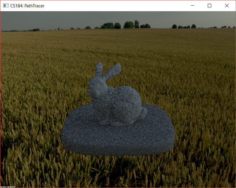

While implementing environment lighting (part 3), I accidentally produced these (incorrect, but) very fabulous bunnies :)